Vertical / Standard
LOAD PATH: PRIMARY
Role in the system
The standard is the upright that carries the scaffold's weight straight down to the ground. Cups are welded along its length at 500 mm intervals, and each cup rotates independently — so up to four ledgers can lock into a single node from different directions without fighting for space.
Two build options are available: a plain end for lighter handling, or a spigot end for a firmer join between stacked sections. Both are formed from 40 mm NB tube with a 3 mm wall, giving the same tube enough strength for load-bearing towers and light-duty access platforms alike.
Because standards ship in a spread of lengths, a crew can combine them to hit almost any working height without cutting stock to size on site.
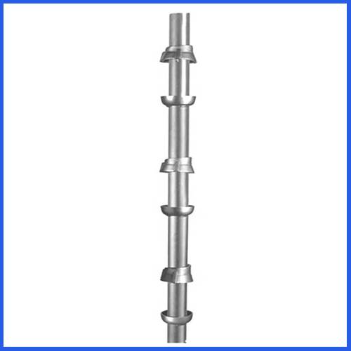
Product Photo — Vertical Standard
Standard Size Details
| Sr. No. | Size (mm) | Weight / Pc |
|---|---|---|
| 1 | 500 mm | 2.2 kg |
| 2 | 1000 mm | 4.4 kg |
| 3 | 1500 mm | 6.6 kg |
| 4 | 2000 mm | 8.8 kg |
| 5 | 2500 mm | 11 kg |
| 6 | 3000 mm | 13.2 kg |
Horizontal / Ledger
LOAD PATH: LATERAL
Role in the system
Ledgers turn a row of standards into an actual frame. Built from the same 40 mm NB, 3 mm-wall tube, each end carries a forged blade that drops into the lower half of a cup and locks with a single hammer strike — assembly is fast, and there's no loose hardware to lose track of.
That connection is what stops the scaffold from racking sideways, so ledgers are doing real structural work, not just filling space between uprights. On stair towers, the same part is reused as a guard rail, giving crews an extra safety layer without adding a separate Rental to the bill of materials.
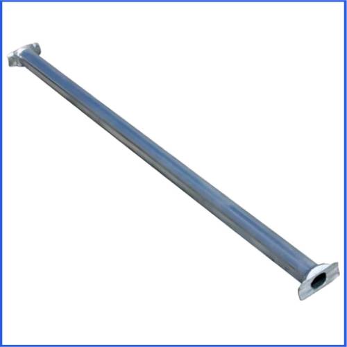
Product Photo — Horizontal Ledger
Fig 02 — Forged blade end detail
Ledger Size Details
| Sr. No. | Size (mm) | Weight / Pc |
|---|---|---|
| 1 | 500 mm | 2 kg |
| 2 | 850 mm | 3 kg |
| 3 | 950 mm | 3.3 kg |
| 4 | 1150 mm | 4 kg |
| 5 | 1450 mm | 5 kg |
| 6 | 1950 mm | 6.5 kg |
| 7 | 2450 mm | 8.2 kg |
Base Jack
LOAD PATH: GROUND BEARING
Role in the system
Few sites are perfectly flat, and the base jack is what keeps a scaffold level anyway. It sits under each standard and spreads the load across a wide steel foot plate so nothing sinks or leans on soft or uneven ground.
A threaded rod and nut let a worker dial in the exact height on the spot, instead of packing gaps with offcuts. It's a small Rental, but it's the one that keeps every standard above it sitting plumb and true.
Build features
- Height adjustment: solid or hollow threaded rod for fine leveling on sloped ground.
- Foot plate: welded 150×150mm or 160×160mm MS plate to spread bearing load.
- Load rating: sized to carry the full vertical weight of the standard above it.
- Finish: painted, galvanized or powder-coated to resist weather and site conditions.
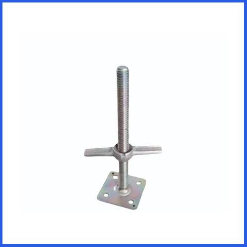
Product Photo — Base Jack
Fig 03 — Threaded rod & foot plate
Base Jack Size Details
| Sr. No. | Rod Type | Rod Dia. | Length | Weight |
|---|---|---|---|---|
| 1 | Solid | 28/30 | 350 mm | 2.8 Kg |
| 2 | Solid | 28/30 | 450 mm | 3.2 Kg |
| 3 | Solid | 28/30 | 600 mm | 4.5 Kg |
| 4 | Hollow | 38 mm | 600 mm | 3.2 Kg |
Stirrup Head / U-Jack
LOAD PATH: FORMWORK SUPPORT
Role in the system
Concrete pours only come out true if the formwork doesn't move — that's the job of the stirrup head. It cradles timber runners, H-beams or steel channels and pins them exactly in place while the pour cures, sitting on top of the standard and locking via a screw rod and nut.
The adjustable design means the same part works across cuplock towers, props and H-frames, so a crew can dial in the right height for different slab levels or beam depths without swapping systems. A galvanized or painted finish means it holds up across repeated job cycles.
Build features
- Alignment: holds beams and slabs steady through the pour with no drift.
- Cross-compatible: fits props, cuplock standards and H-frame legs alike.
- Reusable: designed for repeat use across projects, not single-use.
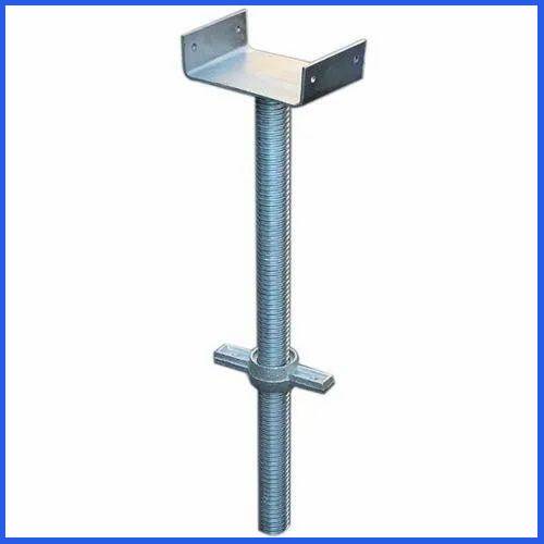
Product Photo — Stirrup Head / U-Jack
Fig 04 — U-cradle beam seat
Stirrup Head Size Details
| Sr. No. | Rod Type | Rod Dia. | Length | Weight |
|---|---|---|---|---|
| 1 | Solid | 28/30 | 350 mm | 2.8 Kg |
| 2 | Solid | 28/30 | 450 mm | 3.2 Kg |
| 3 | Solid | 28/30 | 600 mm | 4.5 Kg |
| 4 | Hollow | 38 mm | 600 mm | 3.2 Kg |
MS Challi
LOAD PATH: WORKING PLATFORM
Role in the system
MS Challi covers two jobs at once: it forms part of the slab and beam formwork, and it gives the crew a stable platform to stand on. Square tubes are welded at even spacing into a rigid mild-steel grid that holds its shape under repeated heavy loading.
Resting on the ledgers and backed by the standards beneath, it keeps a pour aligned while doubling as a safe working surface at height — a simple weld pattern that's proven itself over years of reuse on both small and large sites.
Build features
- Premium mild-steel weld for lasting rigidity.
- Doubles as formwork support and walking platform.
- Quick to install and strike, low cost per reuse.
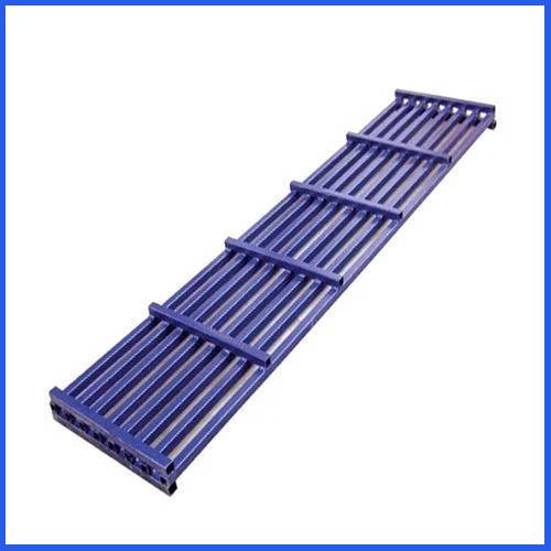
Product Photo — MS Challi
Fig 05 — Welded grid pattern
MS Challi Size Details
| Sr. No. | Size (Ft) | Weight |
|---|---|---|
| 1 | 6 Ft | 12.5 kg |
| 2 | 7 Ft | 14 kg |
| 3 | 8 Ft | 16.5 kg |
Walkway Plank
LOAD PATH: ACCESS SURFACE
Role in the system
Crews need a safe route across a scaffold, and that's the whole purpose of the walkway plank — on new builds, repairs or routine maintenance alike. Made from mild steel, it's rated to take heavy foot and material traffic without flexing underfoot.
Each plank hooks straight onto the ledgers, with welded hooks at all four corners for a fast, secure fit and no loose fittings to manage. The perforated surface adds grip in wet or dusty conditions, keeping the walking surface slip-resistant through the working day.
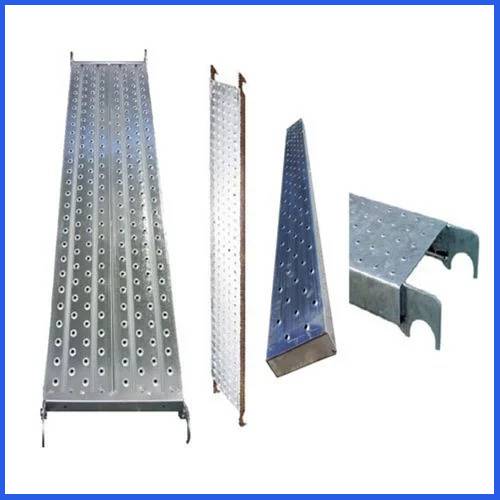
Product Photo — Walkway Plank
Fig 06 — Perforated deck, corner hooks
Walkway Size Details
| Sr. No. | Length (mm) | Weight |
|---|---|---|
| 1 | 1000 mm | 7.5 kg |
| 2 | 1200 mm | 9.5 kg |
| 3 | 1500 mm | 11.3 kg |
| 4 | 1800 mm | 13.5 kg |
| 5 | 2000 mm | 14.5 kg |
| 6 | 2500 mm | 17.5 kg |
Spigot / Joint Pin
LOAD PATH: VERTICAL SPLICE
Role in the system
Tall scaffolds are only possible because of this small connector. The spigot pin joins two standard tubes end to end, turning separate lengths into one continuous run capable of carrying both the downward load and the sideways forces a tall structure faces on site.
Made from mild steel, it's rated to trust with the full weight of everything stacked above it. Because it lets a standard be extended to whatever height the job needs, it's what gives the cuplock system its reach — a small pin carrying a big share of the load, so correct fitting and adherence to site safety practice matters every time.
Function
- Forms a continuous, load-rated vertical splice between tubes.
- Carries both vertical and lateral structural forces.
- Keeps stacked standards aligned and true.
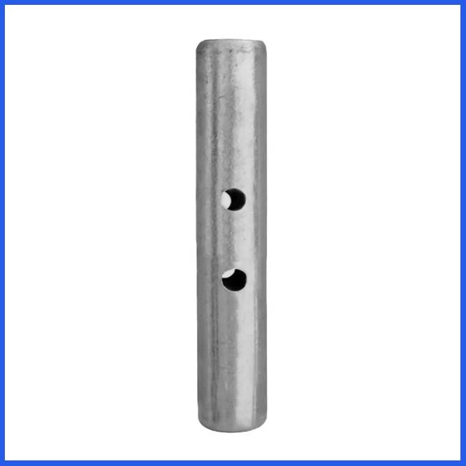
Product Photo — Spigot / Joint Pin
Fig 07 — Internal splice detail
Spigot Pin Specification
| Property | Value |
|---|---|
| Material | Mild Steel (MS) |
| Length | 250mm – 300mm (approx.) |
| Outer Diameter | 38mm |
| Finish | Painted |
| Weight | 500g – 700g |